Project
Large Eddy Simulation of Cycle-To-Cycle Variations in Spark Ignition Engines
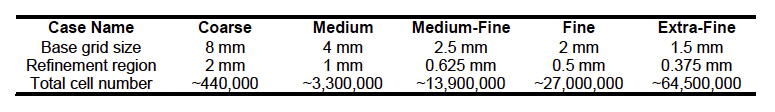 Table 1: Overview of selected grid sizes and total number of cells for grid study.
 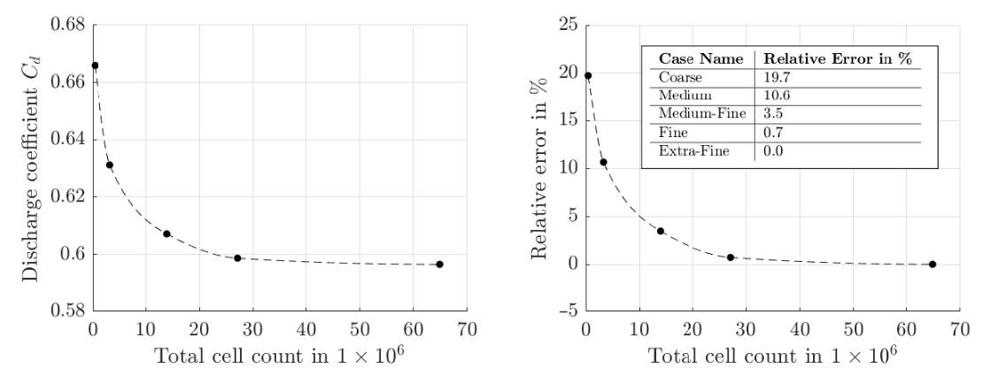 Figure 1: Discharge Coefficient of intake valve in dependence of total cell count (left) and relative error of the discharge coefficient based on the Extra-Fine mesh in dependence of total cell count (right).
 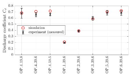 Figure 2: Comparison of simulated and experimental discharge coefficient of the intake valve flow with error deviation of experimental data.
 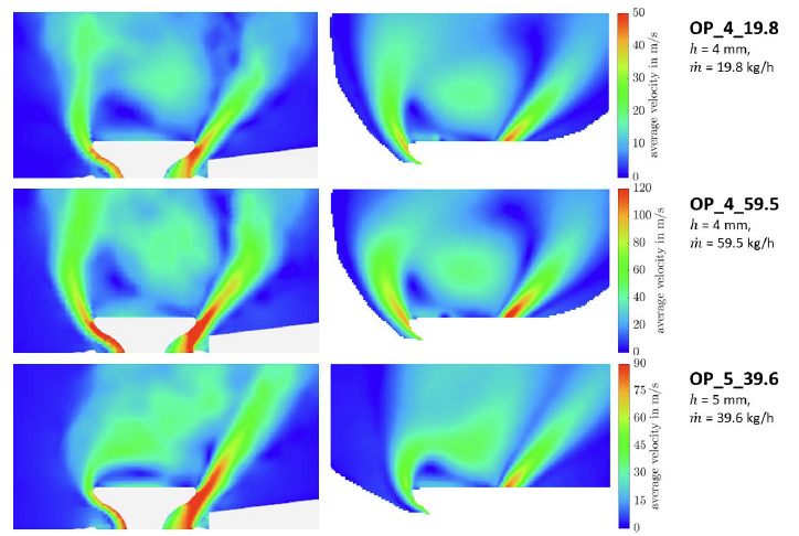 Figure 3: Planar view through intake valve plane with velocity field of LES on the right and PIV on the left. Variation in intake valve lift and mass flow from top to the bottom.
 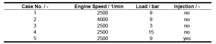 Table 2: Overview of simulated engine operating points of SCE.
 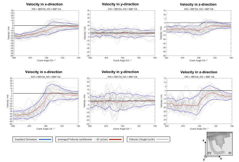 Figure 4: Flow velocity of averaged velocity (red), standard deviation (blue) and single cycle (grey) in the spark plug gap for 30 engine cycles in x-,y- and z-direction. Engine speed of 2500 1/min (upper row) and 4000 1/min (lower row).
 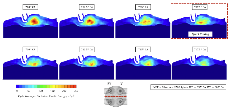 Figure 5: Tumble decease in spark plug plane by evaluation of turbulent kinetic energy around spark timing.
 Due to the necessity to reduce CO2-Emissions and therefore to avoid a worsening in climate change a major contribution in the development of passenger cars is to increase their efficiency. One of the pullbacks in spark ignited engines in this regard are Cycle-to-cycle Variations, which means a variation of the combustion pressure of each engine cycle. These variations make it necessary to diminish the engine limits to avoid for example knocking or misfire and therefore the full potential of the engine cannot be achieved. Main reasons for the different combustion pressures are the homogenization of the air/fuel mixture and the flow field. In this project the focus lies on the analysis of the flow field by using Large Eddy Simulations (LES) to resolve in detail for multiple cycles the flow field of an engine cycle.
Project Details
Project term
December 8, 2021–January 27, 2023
Affiliations
RWTH Aachen University
Institute
Chair of Thermodynamics of Mobile Energy Conversion Systems
Project Manager
Principal Investigator
Methods
LES come along with higher computational effort due to the finer mesh, compared to the more industrial related RANS-approach. Due to the characteristic of RANS-Models fluctuations are not resolved and therefore this method is not adequate and the more computational costly LES will be used. To better understand the flow field and the origin of the cycle-to-cycle variations the project can be subdivided into two tasks. The first task is the validation of the LES methodology on a simplified engine geometry by determining a sufficient accurate grid size to reduce the computational effort for the following Single Cylinder Engine (SCE) LES. The validation will be achieved by comparing simulated results with optical measured data. The SCE of the TME was simulated by 30 engine cycles for 5 different engine operational points by variation of load, engine speed and direct injection.
Results
The evaluation of the grid study in Figure 1 shows with increasing total cell number hence reduced grid size that the discharge coefficient tends towards a limiting value. The absolute change from the Fine to the Extra-Fine mesh is marginal, which is elucidated by the relative error based on the Extra-Fine mesh. The Fine mesh has a deviation of around 0.7% so that the Fine mesh parameters will be chosen for the upcoming parameter variation of the intake valve and the SCE simulations.
For a detailed validation of the LES methodology a parameter variation will be conducted by varying the mass flow and the valve lift of the intake valve to ensure that the LES is capable of resolving multiple different flow states. In Figure 2 the results of the discharge coefficient of the experimental and simulated data are shown, which can be summarized overall as a good agreement of the simulation with the conducted experiments.
Besides the analysis of the discharge coefficient the velocity field in the intake valve plane was evaluated for three different operational points shown in Figure 3. On the left side the temporal averaged velocity field of the LES is shown, on the right side the temporal averaged velocity field of the Particle Image Velocimetry (PIV) measurements. It can be demonstrated that the LES is able to resolve different flow states, which can be seen in the lowest comparison where the left jet snaps off to the right, which was seen in the optical measurements as well. For the other flow states the jet exists straight out of the intake valve gap without distinctive exit angle. With the successful quantitative (discharge coefficient) and qualitative (averaged velocity planes) the grid parameters and the LES methodology was transferred to the SCE simulations. For the SCE LES engine speed, load and the comparison of injection/no injection were simulated. The engine operational points are shown in Table 2.
One focus of the SCE LES was on the flow field condition around the spark plug at spark timing, because these determine the initial flame kernel growth and therefore if there are slower or faster burning cycles. In Figure 4 it can be seen that for lower engine speed the standard deviation is not as high as for higher engine speeds. Furthermore the shown evaluation provide a deeper understanding of the expected flame propagation in space for a certain SCE.
In Figure 5 the Tumble movement and decease around the spark plug is shown. The transformation of bigger turbulent eddies to smaller eddies are increase the flame speed significant and are of great importance for spark ignited internal combustion engines.The averaged turbulent kinetic energy which is directly connected to the appearance of turbulent fluctuations is shown in this figure. It can be seen that the major turbulent kinetic energy is produced close before the spark timing, which could make certain adaptions necessary.
Discussion
In the course of this project, it was possible to substantiate the statement already known from the literature that the load has no influence on cycle-to-cycle variations. In addition, a detailed flow analysis showed that the flow at the inlet valves and the resulting tumble motion have a significant influence on the turbulence level at the ignition point and thus on the resulting combustion. In addition, a standard for SCE LES was established, which was validated on the basis of optical measurement data.
Additional Project Information
DFG classification: 404-03 Fluid Mechanics, 404-04 Hydraulic and Turbo Engines and Piston Engines
Cluster: CLAIX
Publications
Hoffmann J. Mirsch N., Flow Field Investigation of a Single Engine Valve Using PIV, POD, and LES, Energies 2023, 16(5), 2402